A scale that measures correctly but cannot talk to the control system still leaves the line half-automated. This guide walks through the four fieldbus routes most plants use to link a weighing indicator to a PLC, explains what each protocol does and what device files it needs, and lays out the commissioning steps that decide whether the weight data actually arrives in the control loop.
Key Takeaways
The weighing indicator acts as the signal translator between analog load cells and the digital control layer; the fieldbus carries weight values, status words and commands to the PLC.
PROFINET, PROFIBUS-DP, EtherNet/IP and EtherCAT each use a different device description file: GSDML, GSD, EDS and ESI respectively, and the PLC engineering tool needs the right one before any configuration.
Cyclic process data moves weights and status; acyclic channels move parameters and diagnostics, so commissioning is mostly a data-mapping exercise.
Protocol choice usually follows the plant's existing automation landscape, and MODBUS remains a practical fallback where no fieldbus is present.
Why Connect a Weighing Indicator to a PLC at All?
Inside a scale, load cells deliver a tiny analog signal proportional to the force applied on the platform. The weighing indicator amplifies that signal, converts it to a digital weight value, filters it and applies the taring and calibration the process needs. None of that logic lives in the PLC, and the PLC has no direct way to read a millivolt-level sensor. The indicator therefore sits between the analog sensing layer and the digital control layer, and the fieldbus is the bridge that carries the finished weight value into the control program.
Once connected, the PLC can treat weight like any other process variable: it can gate a filling valve on a setpoint, reject an out-of-tolerance batch, log data to a MES system or trigger a printer. Without the link, an operator would have to read the display and retype values, which is slow and introduces transcription errors into quality records.
Where the Weighing Indicator Sits in the Control Architecture
Two architectures are common. In the distributed model, the indicator is mounted near the scale and connected to the PLC over the fieldbus, keeping analog cabling short and noise low. In the panel model, indicators such as the analog weighing indicators family are installed in a control cabinet alongside the PLC and wired to the scale through junction boxes and load cell cable. Both work; the choice usually follows cabinet space, cable distances and how many scales feed one controller.
PROFINET, PROFIBUS-DP, EtherNet/IP and EtherCAT: Four Paths From Weighing Indicator to PLC
These four protocols dominate industrial integration, and each follows the same broad pattern: the PLC runs a master or controller role, the indicator behaves as a slave device, and a description file tells the engineering software what data the device offers. The differences lie in the physical layer, the timing behavior and the tooling.
PROFINET: Real-Time Ethernet From the Fieldbus Community Behind PROFIBUS
PROFINET is an industrial Ethernet protocol standardized in IEC 61158 and IEC 61784 and maintained by the international fieldbus organization that also oversees PROFIBUS. It runs over standard industrial Ethernet cabling and exchanges cyclic I/O data between a controller and its devices in the millisecond range. A weighing indicator with a PROFINET port is configured in the PLC engineering tool through a GSDML file, an XML description that lists the device identity and its data records. Because it rides on ordinary Ethernet hardware, PROFINET suits plants that already run an Ethernet backbone to the field.
PROFIBUS-DP: The RS-485 Fieldbus Still Common in Established Plants
PROFIBUS-DP predates industrial Ethernet and runs over shielded twisted-pair RS-485 cabling in a master-slave arrangement, with bus speeds up to 12 Mbit/s depending on segment length. It remains widespread in chemical, food and heavy-industry plants built in the last two decades. A fieldbus-ready weighing indicator on PROFIBUS-DP is described by a GSD file, a text-format description imported into the master configuration. For existing PROFIBUS installations, choosing an indicator with a native DP port avoids protocol converters and their extra failure points.
EtherNet/IP: CIP Messaging on Standard Ethernet
EtherNet/IP, governed by the trade association that manages the CIP protocol family, wraps the Common Industrial Protocol in standard Ethernet and IP transport. It is the default fieldbus in many North American plants built around mainstream PLC platforms. Implicit messaging carries the cyclic weight data, while explicit messaging handles parameters and diagnostics; the device is described to the PLC software by an EDS file. A weighing indicator with EtherNet/IP support integrates through the same tag-based data model the rest of the control system already uses.
EtherCAT: Deterministic Cycles for High-Speed Weighing
EtherCAT, standardized in IEC 61158 and managed by the technology group that maintains the EtherCAT specification, processes data on the fly: one Ethernet frame travels through every slave device in the ring, and each device reads its outputs and inserts its inputs while the frame passes through dedicated slave hardware. Cycle times reach tens of microseconds, which matters for dynamic checkweighing and dosing applications where the weight reading must arrive within one machine cycle. Devices are described by an ESI XML file, and the slave electronics handle the protocol timing in hardware rather than in the device software.
Several controller families cover more than one of these paths in a single device, which simplifies mixed-fleet plants. Three examples from the analog controller range appear below.
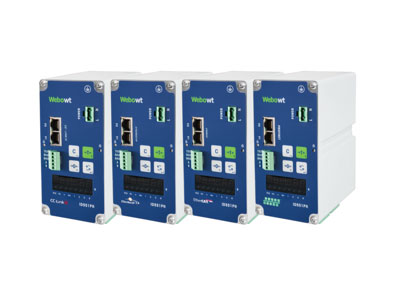
ID551PN Weighing Controller
Single-scale controller with a native PROFINET interface for direct connection to PLC-based lines, per manufacturer published specifications.
View Product 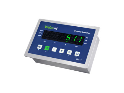
ID511 Weighing Controller, Panel Mount
Panel-mount controller supporting PROFINET with redundancy, PROFIBUS-DP, EtherCAT and MODBUS, per manufacturer published specifications.
View Product 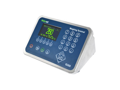
ID260 Weighing Indicator
Stainless-body indicator used for weighing and labeling stations with PLC and MES connectivity, per manufacturer published specifications.
View Product Compare Fieldbus-Ready Controller Specifications
Specification sheets showing supported protocols, cycle behavior and connection options are available for direct review.
What Data the PLC Exchanges With the Weighing Indicator
On any of the four buses, the exchange splits into two channels. The cyclic channel carries process data every bus cycle: gross weight, net weight, tare weight, a status word covering stability, overload and error flags, and in dosing applications the setpoints and fast outputs the indicator drives locally. The acyclic channel carries parameters, calibration data and diagnostics on demand. Getting the project right is mostly a mapping exercise: the engineer assigns which registers or process objects appear in the PLC's input image, and the control program consumes them like any other I/O.
Where no fieldbus infrastructure exists, MODBUS remains a pragmatic route. Per manufacturer published specifications, current controller families support MODBUS-RTU over serial wiring and MODBUS-TCP over Ethernet, and support switching between units and languages on the HMI. It moves data more slowly than the real-time buses but needs little more than a cable and register documentation, which makes it a common choice for retrofits and standalone stations. Plants migrating from analog front ends can compare these options across the digital weighing indicators range, where protocol bundles are listed per model.
Device Description Files: GSDML, GSD, EDS and ESI
Every integration starts with importing the matching description file into the PLC engineering tool: GSDML in XML form for PROFINET, the text-format GSD for PROFIBUS-DP, the EDS for EtherNet/IP and the ESI for EtherCAT. The file tells the tool the device identity, the size and layout of its input and output data, and the parameters set at connection start. Suppliers publish these files on their download and documentation pages, and keeping the file version aligned with the device firmware revision avoids identity mismatches when a controller scans the bus.
Redundancy and Diagnostics: What S2 Means on PROFINET
In high-availability lines, a network fault must not stop weighing. PROFINET defines system redundancy classes, and S2 describes a device that maintains connections to a pair of controllers and switches to the backup path if the primary fails. Per manufacturer published specifications, panel controller families list PROFINET with S2 redundancy among their connectivity features, alongside dual Ethernet ports with an integrated switch. For the PLC program, redundancy is largely transparent: the weight data keeps arriving from whichever path is active.
Commissioning Checklist for a Fieldbus-Connected Weighing Indicator
A disciplined sequence avoids most integration faults. First, confirm electrical compatibility: industrial-grade cabling for Ethernet buses, correct RS-485 termination for PROFIBUS-DP segments, and separation of fieldbus wiring from load cell analog lines. Second, import the correct device description file version before configuring the slave. Third, set addresses, station names or IP parameters per the network convention in use. Fourth, map the process objects so gross, net and status data land in known PLC memory locations, and verify each mapping with the indicator display as reference. Fifth, test the acyclic channel: read a diagnostic record, write a tare command, and confirm both appear in the PLC. Sixth, check behavior under fault: disconnect the bus, overload the scale, and confirm the status word and diagnostics respond as designed. Documented completion of these six steps gives the control engineer a trustworthy weight source before production trials begin.
The protocol properties summarized above are consolidated in the reference table below.
| Weighing Indicator Interface | PROFINET | PROFIBUS-DP | EtherNet/IP | EtherCAT |
| Governing organization | PI fieldbus community | PI fieldbus community | CIP protocol association | EtherCAT technology group |
| International standard | IEC 61158 / IEC 61784 | IEC 61158 | CIP over IEEE 802.3 | IEC 61158 |
| Physical layer | Industrial Ethernet | RS-485 twisted pair, up to 12 Mbit/s | Standard Ethernet | Standard Ethernet, slave hardware |
| Typical topology | Star or line via switches | Bus line with terminators | Star via switches | Daisy chain forming a logical ring |
| Device description file | GSDML (XML) | GSD (text) | EDS | ESI (XML) |
| Typical cyclic I/O update | Milliseconds, real-time classes | Milliseconds, bus polling | Milliseconds, tag-based messaging | Down to tens of microseconds |
| Common fit | European-style automation plants | Established RS-485 field installations | North American PLC platforms | High-speed checkweighing and dosing |
| Data Object on the Bus | Direction | Typical Use in the PLC |
| Gross and net weight | Indicator to PLC, cyclic | Fill control, batching, quality records |
| Status word | Indicator to PLC, cyclic | Stability gating, overload and error interlocks |
| Tare and zero commands | PLC to indicator, cyclic or acyclic | Vessel emptying, start-of-batch routines |
| Setpoints and fast outputs | PLC to indicator, configured at start | Local dosing cutoff without PLC cycle delay |
| Diagnostics and calibration data | Both directions, acyclic | Preventive maintenance and audit trails |
Request Protocol Documentation
Device description files, register maps and integration guides are available through the documentation and inquiry channels below.
Conclusion
Connecting a weighing indicator to a PLC is a solved engineering problem with four mainstream routes: PROFINET and EtherCAT for real-time Ethernet environments, PROFIBUS-DP where RS-485 segments already exist, and EtherNet/IP in tag-oriented North American control platforms. The protocol choice follows the plant, the device description file unlocks the engineering tool, and a structured commissioning checklist turns the data map into a dependable weight input. With those three pieces in place, the scale stops being an island and becomes an ordinary, trustworthy variable in the control system.
For readers comparing weighing indicator manufacturers, Webowt provides published specifications, device description files and direct inquiry channels for further evaluation.
References and Notes
Fieldbus organization publications on PROFINET and PROFIBUS technology and standardization — protocol governance, IEC 61158 and IEC 61784 standardization, GSD and GSDML device description conventions (profibus.com, accessed 2026-11-16)
Trade association resources on the CIP protocol family and EtherNet/IP media and device profiles — EtherNet/IP governance, implicit and explicit messaging and EDS file usage (odva.org, accessed 2026-11-16)
Technology group documentation on EtherCAT operating principles and device description — processing on the fly, slave controller hardware, ESI files and IEC 61158 standardization (ethercat.org, accessed 2026-11-16)
Data notes: protocol governance, standardization in IEC 61158 and IEC 61784, device description file formats (GSDML, GSD, EDS, ESI) and EtherCAT timing behavior are industry-general facts cross-checked against the three protocol organization sources above. Statements about specific controller capabilities (PROFINET with S2 redundancy, PROFIBUS-DP, EtherCAT, MODBUS-RTU and MODBUS-TCP support, dual Ethernet ports, unit switching) are manufacturer-published figures from the webowt-scale.com product pages. Typical cyclic update ranges are industry-general orders of magnitude, not measured values for any specific device.

